
大家好,我叫 Bobby,来自泰国。
Gripper.vcmx(1.3 MB)
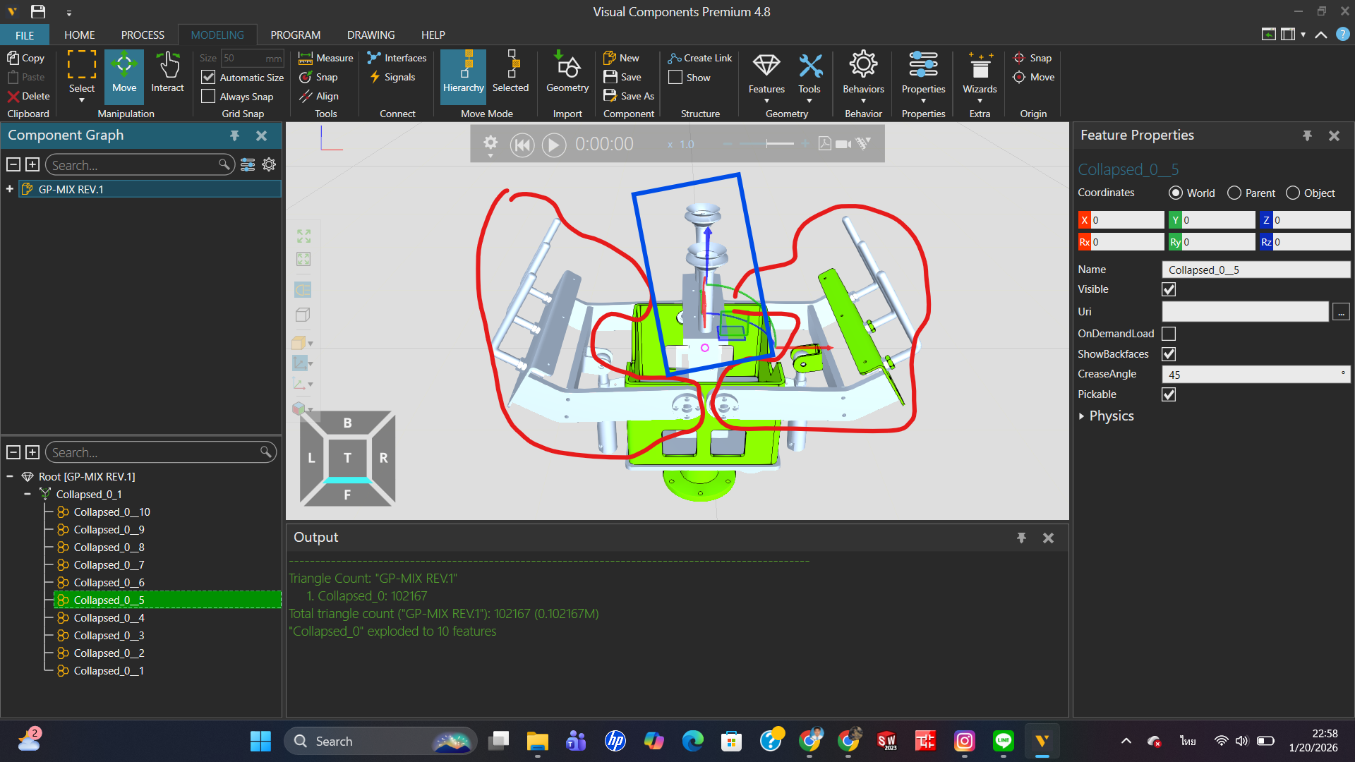
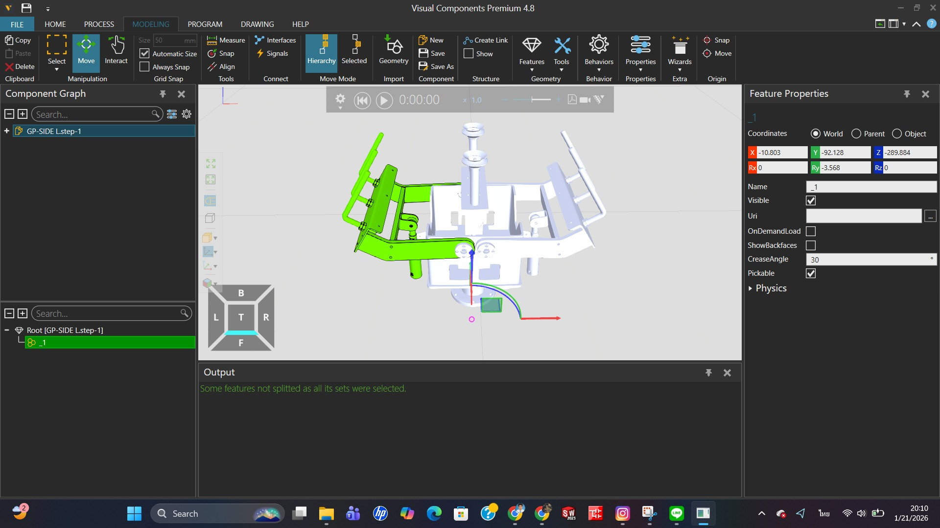
我目前在夹爪建模时遇到了一个问题。将 CAD 文件导入软件后,当我尝试选择应该移动的连杆或关节时,程序并没有将它们识别为一个单一连杆,而是将它们当作独立的零件。
因此,我不确定应该如何设置或组织模型结构,才能使软件将这些零件识别为一个连杆。
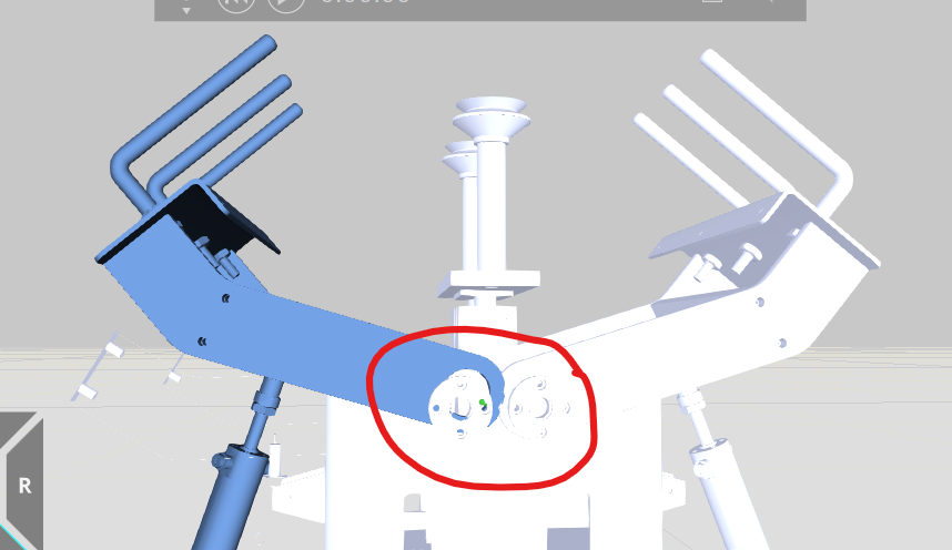
详情请见附图。
恳请阅读本话题的各位专家不吝赐教与指导。非常感谢!
大家好,我叫 Bobby,来自泰国。
Gripper.vcmx(1.3 MB)
我目前在夹爪建模时遇到了一个问题。将 CAD 文件导入软件后,当我尝试选择应该移动的连杆或关节时,程序并没有将它们识别为一个单一连杆,而是将它们当作独立的零件。
因此,我不确定应该如何设置或组织模型结构,才能使软件将这些零件识别为一个连杆。
详情请见附图。
恳请阅读本话题的各位专家不吝赐教与指导。非常感谢!
你好,Bobby,
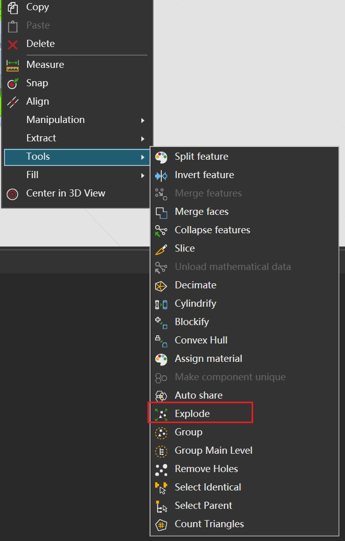
我没太明白你的主要问题是什么,所以我们逐一来看。因为 VC 与其他 CAD 建模软件不同,它更偏向于视觉效果类软件(在操作原理上)。所以,进入 VC 的通用模型都需要经过 CAD 转换。建模或转换过程中出现的任何依赖项或问题,都可以归结为模型外部的问题。这时,你可以尝试右键菜单中的“分解”选项,程序会尝试将模型拆分成更多特征。当然,这种方法并不总是有效,所以还是要注意建模习惯。
希望这能帮到你。
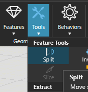
很好的回答 @BAD。另外,“分割”工具对于从较大的几何特征中分离出几个特定几何形状也很方便:选择“分割”,然后点击三维世界中你希望作为独立几何特征的对象。
你好,
从你的描述和图片来看,你希望将多个几何对象合并为一个单一的连杆(link),但使用“分解”(Explode)功能后,软件仍然无法将它们识别为一个整体。这通常是因为分解操作会将组合对象拆分为独立的几何体,而不是将它们合并。
要解决这个问题,你可以尝试以下方法:
1. **使用“合并”(Combine)或“布尔运算”(Boolean Union)功能**:
在大多数CAD软件中,你可以通过布尔运算(如“并集”)将多个独立的几何体合并为一个单一实体。具体操作步骤可能因软件而异,但通常可以在“修改”或“编辑”菜单中找到相关选项。
2. **创建组件或装配体**:
如果软件支持,你可以将多个几何体组合成一个组件(Component)或装配体(Assembly),然后将其定义为一个连杆。这样,软件会将它们视为一个整体进行运动模拟。
3. **检查几何体是否完全连接**:
确保所有几何体之间没有间隙或重叠问题。如果几何体未完全接触,合并操作可能会失败。你可以使用“修复几何”工具检查并修正问题。
4. **使用“分组”(Group)功能**:
某些软件允许将多个对象分组,使其在运动模拟中作为单一对象处理。虽然这不是真正的几何合并,但可能满足你的需求。
5. **参考教程中的方法**:
你提到的机器人夹爪教程可能提供了更具体的操作步骤。建议重新查看教程,确保你正确设置了连杆的关节类型(旋转关节而非平移关节)和位置(旋转轴位置)。
如果你能提供更多关于所用软件的信息(例如:SolidWorks、Fusion 360、visual Components等),我可以给出更具体的指导。希望这些建议能帮助你解决问题!
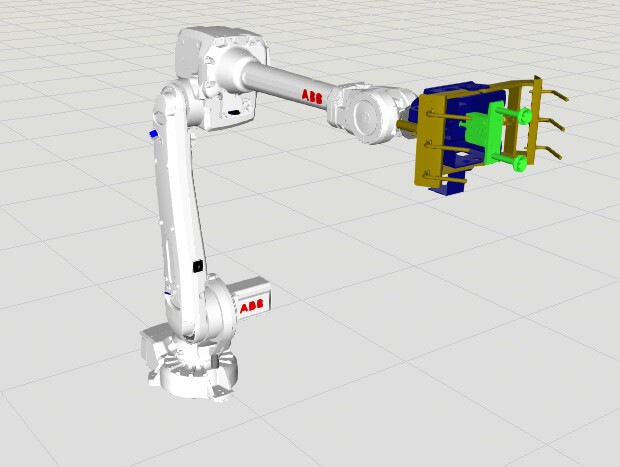
@bobby_RMUTTO67,你可能已经看过这个教程了,但它会指导你完成机器人夹爪的建模:Model a Robot Gripper – Part I | Visual Components Academy
唯一不同的是,现在夹爪的活动连杆的关节类型应为“旋转关节”而不是“平移关节”,并且连杆的位置必须位于旋转轴所在的位置,这样连杆才能绕正确的轴旋转。
你好,@KustiH,我已经看过这个教程视频,但当我尝试跟着操作时,我的结果和视频里的不一样。我以前从未使用过“分割”命令,但我会试着用一下。
感谢您的回答,感谢您的帮助。非常感谢。
好的,Bobby,
我先补充一下之前回复的内容。当某个不应被视为特征的组件被错误地识别为特征时,可以使用这种分离技术。我注意到你提到想把多个元素当作一个整体来处理——要合并多个原本不是统一特征的元素,你可以使用“合并特征”功能,这个功能也在我之前展示的右键菜单里。另外,你可以对已移动的特征使用“折叠”功能,将其合并成一个单一特征。需要注意的是,几何元素特征和可调整的参数化特征(例如正方形、圆形等)不能直接用“合并特征”功能合并。你需要先用“折叠”功能将参数化特征转换为几何元素特征,然后再进行合并。
以上是我对你关于“将元素视为一个整体”这个问题的回答。我不确定这是否完全满足了你的需求,但我可以确认这个方法是有效的。
顺便说一下,生成链接时同样使用右键菜单——但它不在“工具”子菜单下,而是位于“提取”选项中,即“提取为链接”。
晚安,希望这对你有帮助!
如果我没理解错你的问题,你不需要把运动部件合并成一个几何特征。几何体可以保持多个部分,关键在于所有需要一起运动的部件都放在同一个关节下。
使用分解或切割功能将CAD模型拆分成需要的部分。然后选中应该一起运动的部件并提取为链接。该链接下的所有部件将作为一个整体运动。
从你的图片来看,你可能需要将左右夹爪部分设为两个独立的链接。然后对其中一个链接应用旋转跟随器,这样两侧就能保持同步运动。
@bobby_RMUTTO67,BAD 说得对,希望这能帮你提供更多背景信息。
远程桌面支持 一般问题 amlandis3 2021年6月11日 上午4:341 为什么我们不能在Visual Components中使用远程桌面?...
2026-04-21visual Component General Questions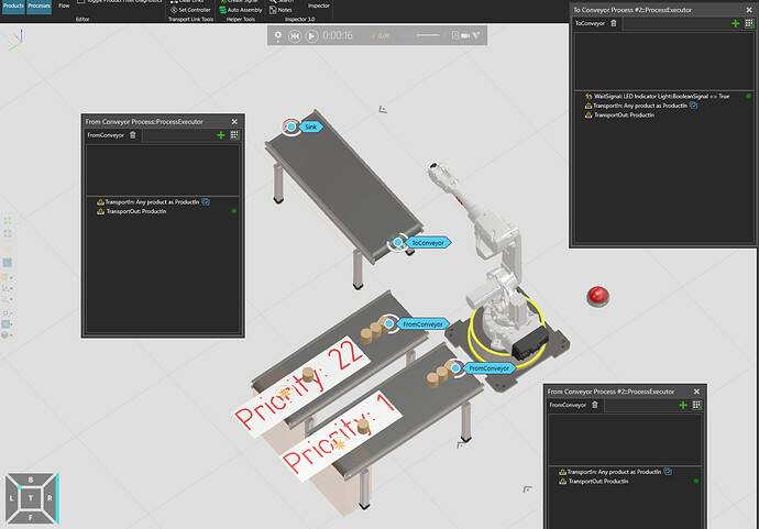
hans 2026年4月10日 上午7:211 关于进程转换的问题优先级。请看以下案例:...
2026-04-21visual Component Process Modeling
PartCreator 扩展与Python插件...
2026-04-21visual Component Extensions and Python Add-ons
jurel 2025年11月5日 上午8:171 你好, 我还有一个...
2026-04-21visual Component .Net Add-on Programming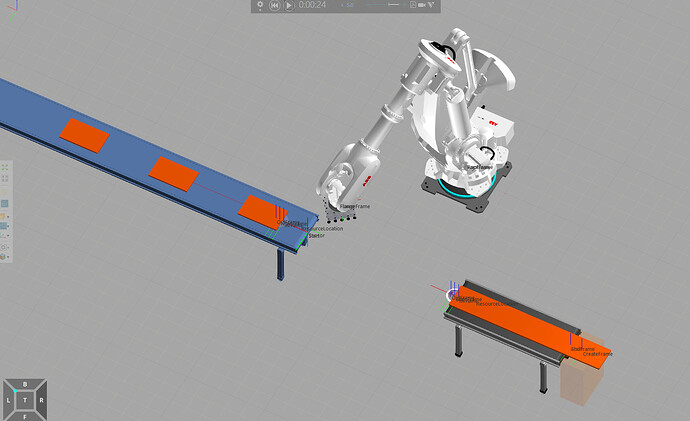
RaycastSensor 无法正常工作的常见原因及解决方案 1. 配置问题 传感器未启用:确保在代码或配置文件...
2026-04-21visual Component Process Modeling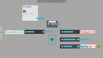
在手动流程中将产品装入容器作为装配 流程建模 中...
2026-04-21visual Component Process Modeling
我想请教一下,在VC5.0中如何使用MBD自动生成焊接程序。...
2026-04-21visual Component Robot Programming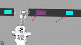
汉斯 2026年3月24日,下午2:301 我已在通用传送带上添加此脚本,用于监听产品被添加到传送带路径...
2026-04-21visual Component Python Programming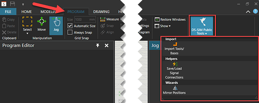
mastu 2023年5月10日,下午2:261 如果您在 KUKA.Sim(插件)或 KUKA OLP...
2026-04-21visual Component Extensions and Python Add-ons
上网淘巴领天猫淘宝优惠券,一年省好几千。
广告 ×您是本站第1407689名访客 今日有0篇新文章/评论


 微信扫一扫,打赏作者吧~